SET UP
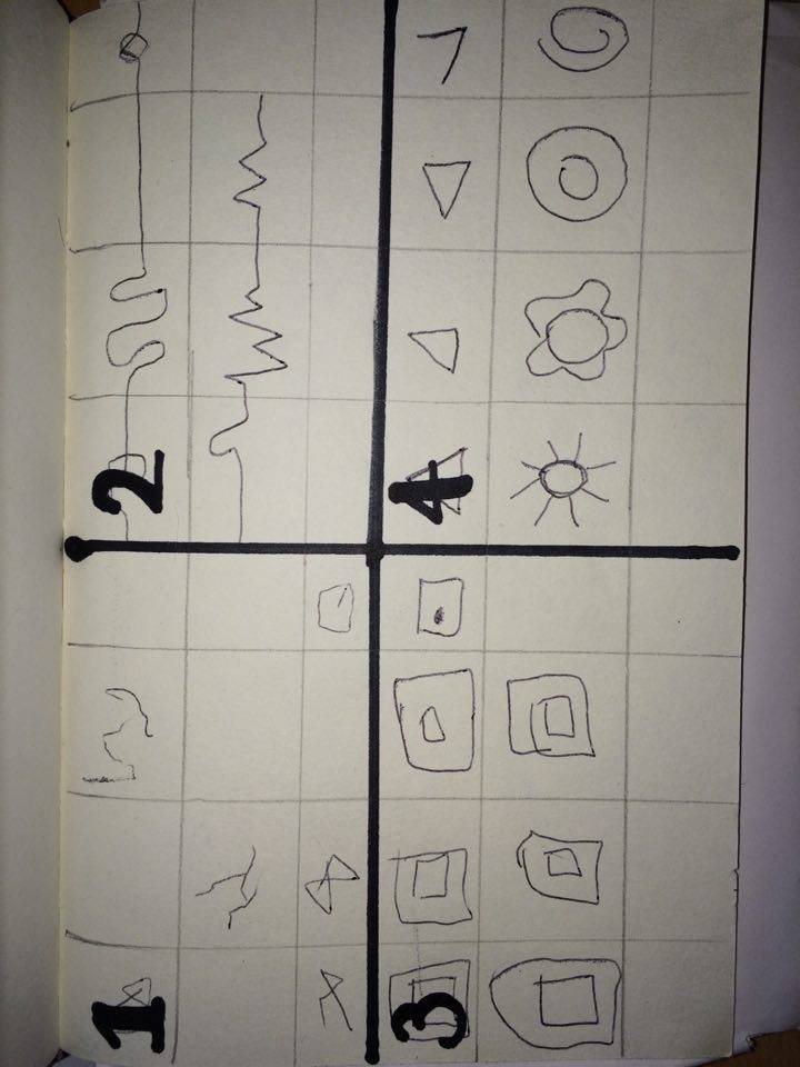
Once we had decided on the direction of our project, and in what style we wanted to present it, we then had to design the layout of the installation.**talk about in research about other layouts** Knowing that we wanted to project onto a larger screen, and control the hardware form a stand we wanted to make sure we has an open space. Therefore we began by mocking up what the exhibition space would look like:
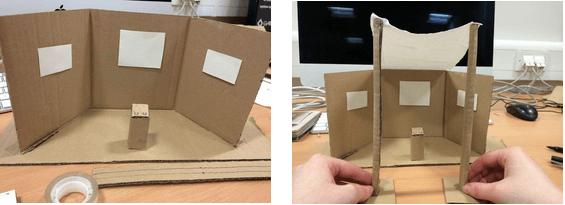
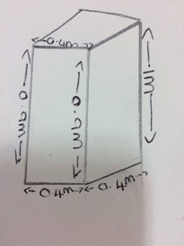
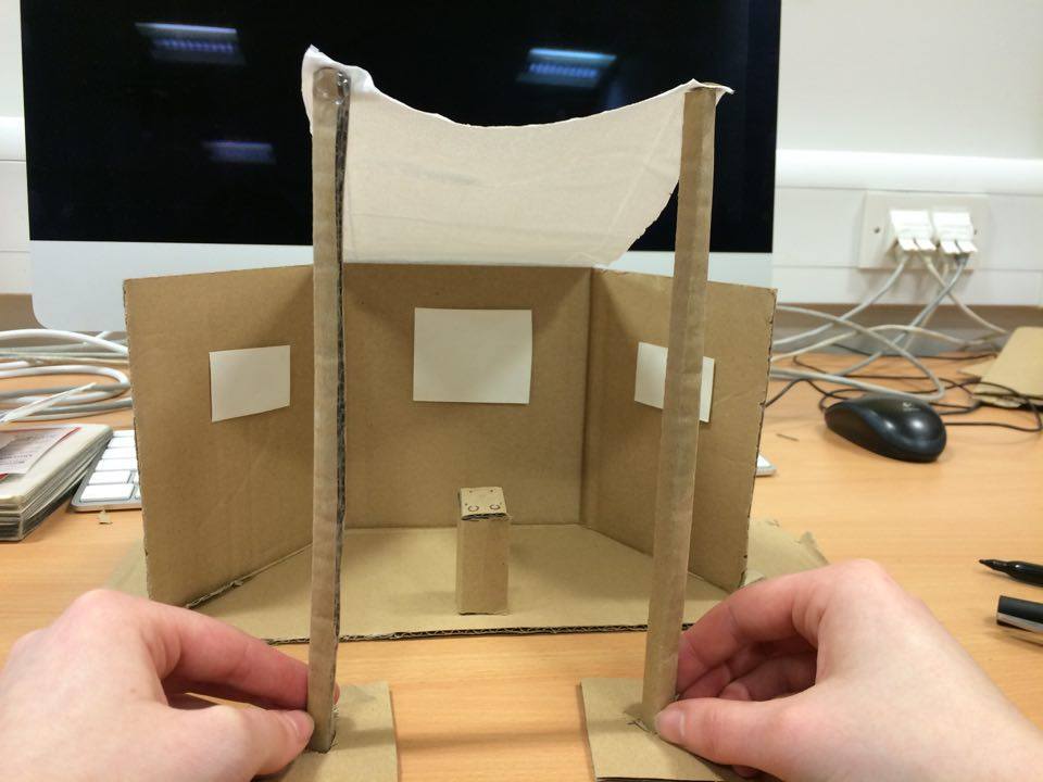
With the box directly in front of the screen, we wanted to enclose the screen to make it more immersive. Therefore we designed the space to have either boards or material to hand either side of the screen. This was however at an angle so that the space was not completely boxed in. After creating the rough mock up, we then drew it out trying to estimate rough measurements.

When it came to creating the installation we focused on 3 main parts;
- The display
- The box
- The installation
The Display
Due to the space that we used, we decided to use the large screen provided instead of projecting onto a wall. This meant that we also then didn’t have to worry about placing a projector within the installation.
The Box
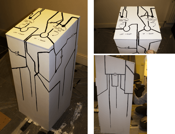
In order to create a platform for the users to interact with, we decided to create a podium that would sit at an easy height for everyone.
In the design of the podium, we first of all thought about how it could be created in order for the easiest use. Therefore we decided create it on a slant. This means that the top of the podium where the controllers would be, were easier to see rather than having to look straight down. This also made it easier for the user look at the screen as well as use the controls. Height wise we needed it to be suitable for everyone, therefore we made it 0.9-1m.
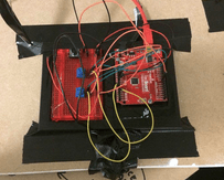
To create the box, we used thin wooden boards.the slats were then cut into 5 different pieces and nailed together in order to create the frame. Extra wooden slat were attached to the back for extra support. The top was kept separate, and sit on top of the box by having 4 small piece of wooden in place to stop it moving around when placed on top.
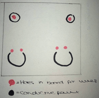
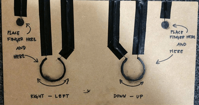
Once the structure was made, we then had to create small holes on the top board in order to push wires through. There were 2 towards the top, 1 left and 1 right. These were for the wires that connect to the A0 and A1 ports on the arduino to get the reading. These was also 2 holes lower down on the left. The left hole was for the + wire and the right for – wire. This was replicated on the right hand side of the board the same way. This created our 2 controllers. Once the were through they were covered in conductive paint to make the circuit. This also covered them up so they were not obvious to the users. The save button was taped to the top of board. This was because we could not create a hole large enough for
The wires were then connected to the arduino board as they would be normally, and the arduino board was duct taped to the bottom of the board.
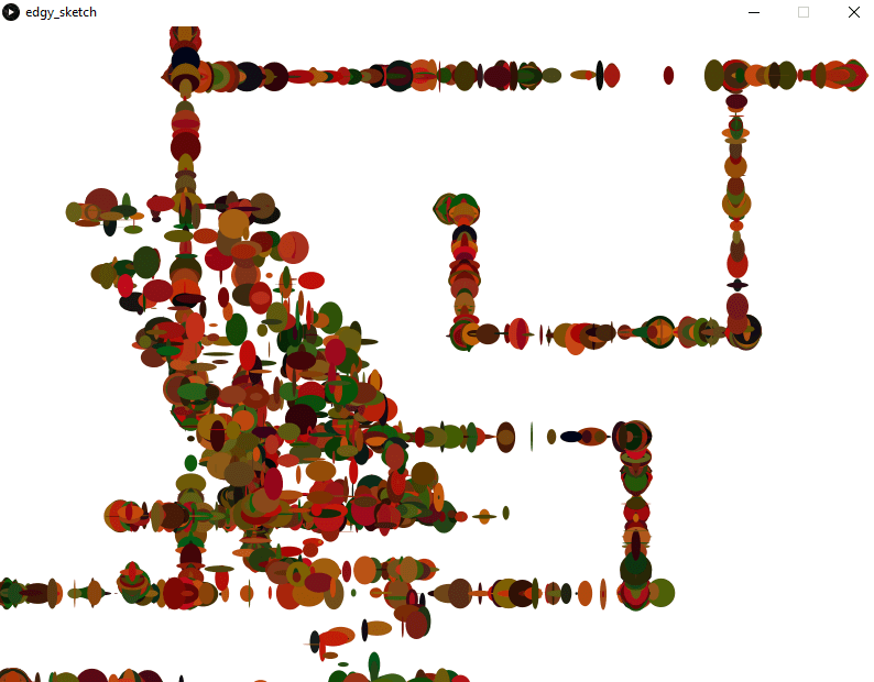
For decoration of the box, we wanted to try and immerse the conductive paint into the design. Therefore we painted the whole box white to make the black conductive paint stand out. The conductive paint was then applied and instructions were put next to the with a black marker to make them clear. We then added a line effect based on the idea of lines from an etch-a-sketch. This however turned out to look more like wires, and therefore we decided to incorporate circuit symbols within the design.
This made the box stand out as a piece of the installation on it’s own, as well as fitting in with the concept of the project.
The Installation
Once the box and display had been created, we could then set up the installation. With the screen already in place, we could place the box the suitable distance from the screen. With this as our base we could put up the side of the installation. Instead of using boards for this, we hung plain white material either side. This made it cheaper and easier to set up.
Once the structure was made, we could then set up the laptop. This was sat inside the podium so it was close enough to connect to the arduino, but also hidden away. We then ran a wire from the laptop to the wall directly in front of the podium, under the screen to connect the laptop to the screen. This was duct tape down in order to avoid a trip hazard.
To light the installation without it being too light so that the screen wouldn’t stand out, we hung fairy lights across the top and down the side of the installation (closest to the podium). This meant there was enough light to be able to see the controls on the box clearly, but also meant that the screen stood out. It also made the installation itself look more aesthetically pleasing and immersive.
*The fairly lights broke when originally out up, but with the use of conductive paint to reattach the wires they we were able to use them still*
We also put posters with the benaging on inside and otuside the room in the hope to draw people in. It also put a stamp on the product and perhaps even promoted it.
RUNNING THE INSTALLATION
Whilst the installation was being exhibited someone always had to be present. This was due to a number of reasons
- To greet people when they entered and welcome them to the installation
- To instruct them on the use of the piece
- To make sure that they knew to always keep their fingers on the 2 points
- To restart the board for the users if they were unable to due to having to keep their fingers on the board.
- The software crashed or their were any issues with the wiring
- The make sure the screen didn’t go black during the use of the arduino.
Reflection
From running the installation there were a few issues that we found with both the set up and the technology.
- Due to the conductive paint, when people have finished with the piece they ended up with black finger tips. This was also smudged on the board itself. Whilst this didn’t affect the running of the installation itself, it was an inconvenience for the users. It also messed up the design of the board. Therefore if this was run again we would look at either putting a clear topping or an acrylic paint over the top. This wouldn’t effect the conductive paint, but may stop it from rubbing off on anyone.
- At the start the laptop that was being used crashed twice. Although we had another laptop to run it off, this meant that we had to run the whole installation in hope that the other didn’t crash. Whilst we did have a backup, this still took time to set up as we were not prepared for the first to crash. Therefore next time it would be more efficient of us to have the backup ready to use at any point. We could not however find the reason why it crashed meaning we can not change anything to avoid this happening again.
- The computer also turned of when not in use for a while. This meant they whilst people were drawing, the screen would sometimes go black. In the end we just have to keep remembering to shake the laptop in between users. However if this was run again, we would hopefully find a way through the computer to keep it running at all times without having to keep shaking it,
- As previously said, whilst the installation was being exhibited someone always had to be present. If this was to be displayed again or as part of a different exhibition, the possibility of always having someone there may not be an option.
- Whilst the white sheets worked effectively. Perhaps using boards next time would make it into a more immersive and professional installation.
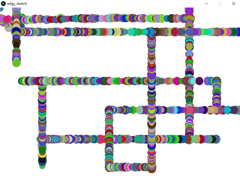
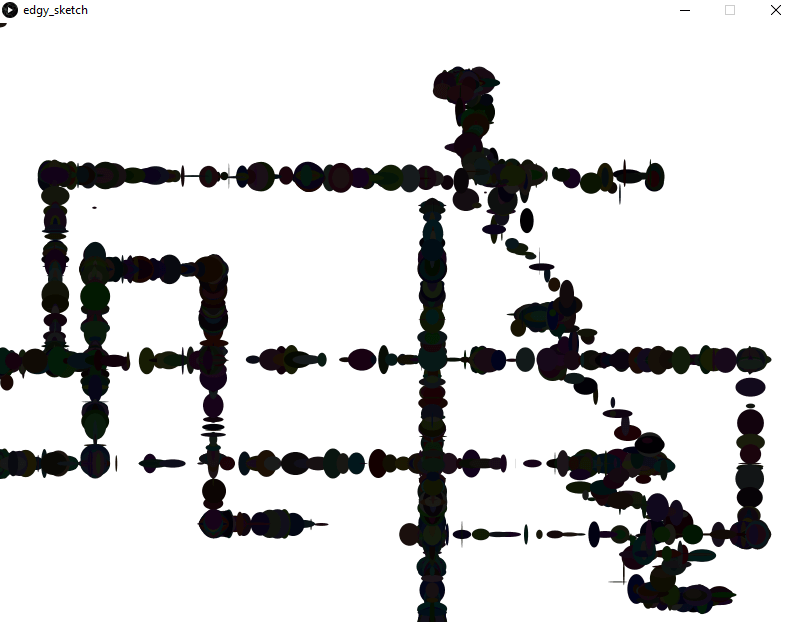
- Whilst we were saving the images people created, there was no way for people to see them after they had finished or to see others. Therefore next time we would hope to have more screens in order to show a platform that would display all our pieces.
Recent Comments