fill (random (colour));

We’ve been experimenting how we can make the sketch look more interesting. By adding these two lines:

fill (random(200), random(100), random (30));
ellipse (penX, penY, random(30), random(30));

to our code with in “void draw() { }” we can now change the ellipse and the fill of our pen.

We started of with randomizing the ellipse. As you can see it changes from a size of 0 to the maximum size.

ellipse (penX, penY, random(hight), random(width));

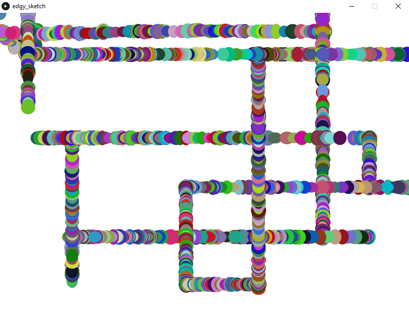
Next we changed the colour, this works on a RGB scale.

fill (random(255), random(255), random (255));

knowing that both worked we now started changing the values. For example:

ellipse (penX, penY, random(200), random(200));

This changes the max. value that we created earlier to 200.

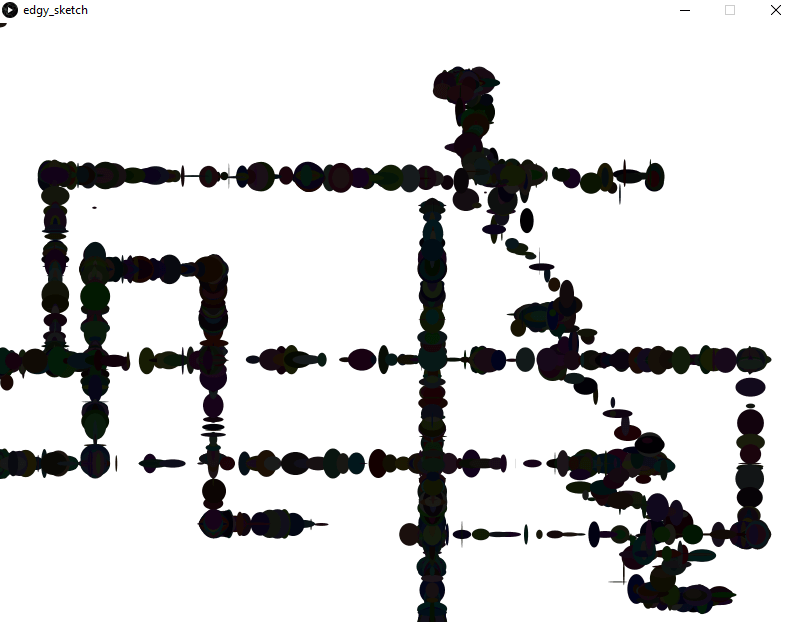
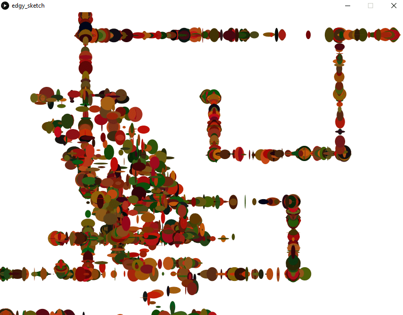
Other changes where:

fill (random(255), random(255), random (255));
ellipse (penX, penY, random(20, 30), random(20, 30));

Screenshot (45)

fill (random(50), random(50), random (50));
ellipse (penX, penY, random( 30), random( 30));

Screenshot (46)

fill (random(200), random(100), random (30));
ellipse (penX, penY, random(30), random(30));

Screenshot (47)

Concept Development

The Concept

To be more than just a sketch, we wanted to take the project further. With a key idea of co-operation being at the heart of the project, we developed ways to incorporate this into our piece further.
Therefore we elaborated the concept of creating a single piece between two people and decided to create a whole piece of artwork based on everyones collaboration. By this we mean, every piece that is created gets saved. This piece will then be put into a grid and eventually will create a large build up of numerous peoples work in order to create a final piece.


Potential Ideas

12939607_10156784750500287_1511018388_n

1. Each sketch is done however the participant wants and is randomly added to the grid
2. The participants are given a start and an end point, then their image is added to the grid giving the over all image a connection between each image
3. Everyone is asked to try and draw the same image. When done the image is added to the grid on any order.
4. Like the concept of Chinese Whispers, the first people are given an image to try and imitate. The person after them then copies the previous sketch and so on. This is completed for each line of the grid or potentially the whole grid till complete. 


Chinese Whispers

The Chinese Whispers idea is the one that we found worked the most. not only does it make the sketch fun and create a nice final piece at then end. It also takes aspects of collaboration in the use of the interactivity. For example;
– To draw the sketch it will still require 2 people to make one image
– the following on form the last drawer means that whilst your pair is working separately, you will still be relying on the first person to know what to draw
– Whilst you work individually, you will essentially be working as part of a whole int he end piece.

The grid will be either 8×8-10×10


Installation Design

If this idea was to be used, the way the installation would be set up would be such as;
12966334_10156784895590287_1376930932_n

There would be a screen on the left that showed what the participants where suppose to try and draw.
The screen in the middle would project what is being drawn
and the screen on the right would show the grid (although this may be done different to stop people seeing the original drawing they are meant to be imitating.)

The post in the middle would be what holds the ardunio and has the control on top. The projector will also be in this post.

The video gives a idea of how it would be seen from the participants;


The post in the middle will consist of;
– Controllers (Circles) to guide the pen left, right, up and down
– Symbols to show users what controllers are what
– A button to clear the screen 
– A button to save finished sketch
– The ardunio board and laptop underneath the wood
– The projector

branding mock up

This is just a quick mock up of how the logo could be used on a business card. The fonts used are Big John and Slim Jim which go nicely with the logo.

business_card_back-01-01


business_card_front-01

edgy_sketch_bcmockup

Logo and Name Development


We know what we want the style of the logo to look like, namely a rough paint brush kind of style. Now we need the actual logo and a name for our product. The picture below shows a few first sketches and key words we could use.

logo_sketch_01

Leading on from this and influenced by our current visuals of the processing code, we came up with a very abstract logo idea. The circle is representing the circuit and our controls for the new etch a sketch, whilst the lines in the centre are a representation of a sketch.

logo_sketch_02

logo_sketch_vec-03

An abstract logo allows us to still think of a name. Following is a list of keywords that we could combine to name our product. We tried differnt variations but non of them were quite what we were looking for.

– Art

– Paint

– Brush

– Sketch

– Line

– Draw

– Play

– Game

– Retro

– Modern

– Combine

– Morph

– Scattered

– Altanative

– Create

– Collaborate

– Interact

– Finger

– Body

– Circuit

– Arduino

– Electronics

– Digital

– Cardboard

Finishing our little session Jas described our project as “edgy” -> “Edgy Sketch” (Saaayyy whhaaattt???)

We are well aware of it beeing a terribly cringy name but at the same time it gives it the certain something we need for people to remember it. I’m not saying it is the final name but it is the best we have at the moment. So going for the same style as already shown in example above and with the name “edgy sketch” we created some more logo sketches:

logo_sketch_03

logo_sketch_04

logo_sketch_05

…which I then converted in to vectors which look like this:

logo_sketch_vec-02  logo_sketch_vec-04logo_sketch_vec-01 logo_sketch_vec-05

Sketch & Conductive paint

TEST 1

Original Test

To begin we reran the original controls. 


REFLECTION

+ Works well

Boring to use, not very exciting

Switches are difficult to use as too small and close together.


TEST 2

Using Paint to the X axis controller

By creating a straight line and placing the 5V wire at one end and the GND at the other/ the middle wire (A0) is held.


REFLECTION

+ Works well

 Still only 1 off the board

 Couldn’t use the whole screen


TEST 3

Using paint for the X and Y axis controller.

By replicating the same process as before for the other controller. this created reading for the Y axis s well.


RESULT

Test_3


REFLECTION

+ Works well

 Wouldn’t always use the full screen

 Was very jumpy, didn’t draw in straight line as it did before meaning the image would be distorted.
(however, this could be a good as it makes it more arty/ abstract, giving the piece some originality.)


TEST 4

Making the paint controllers circular

By simply drawing the paint into circular shapes and applying the wires in the same way.


RESULT

Test_4

REFLECTION

+ Works well

+ Bigger range across screen

+ the shape of the controllers are more representative of that on an original etch-e-sketch

 Still Jumpy


TEST 5

Using 2 people to control one axis

Person one; holds middle wire and person 2’s hand

Person two; holds person ones hand and moves their figure across one of the controllers

(test around with having to hold the wire connected to circuit.

IMG_0009 IMG_0011

RESULT

Test_5

REFLECTION

+ Works well

+ Bigger range across screen

+ Fun and requires co-operation

 Still Jumpy


REFLECTION 

The paint has been inputed into the circuit well. The shape makes it more representative of the old style as well as more responsive on the screen.

The controllers are still quite small though.

one other concern is that the middle wire requires it to be held to draw. This may be an inconvenience to the person using it.