Concept Development

The Concept

To be more than just a sketch, we wanted to take the project further. With a key idea of co-operation being at the heart of the project, we developed ways to incorporate this into our piece further.
Therefore we elaborated the concept of creating a single piece between two people and decided to create a whole piece of artwork based on everyones collaboration. By this we mean, every piece that is created gets saved. This piece will then be put into a grid and eventually will create a large build up of numerous peoples work in order to create a final piece.


Potential Ideas

12939607_10156784750500287_1511018388_n

1. Each sketch is done however the participant wants and is randomly added to the grid
2. The participants are given a start and an end point, then their image is added to the grid giving the over all image a connection between each image
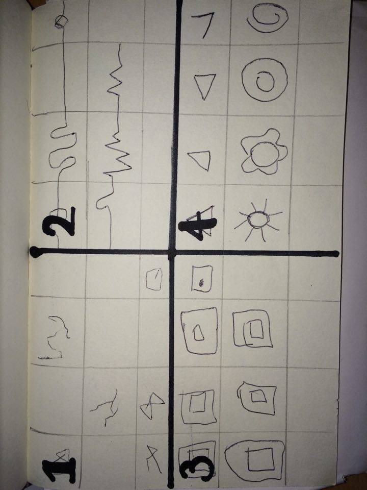
3. Everyone is asked to try and draw the same image. When done the image is added to the grid on any order.
4. Like the concept of Chinese Whispers, the first people are given an image to try and imitate. The person after them then copies the previous sketch and so on. This is completed for each line of the grid or potentially the whole grid till complete. 


Chinese Whispers

The Chinese Whispers idea is the one that we found worked the most. not only does it make the sketch fun and create a nice final piece at then end. It also takes aspects of collaboration in the use of the interactivity. For example;
– To draw the sketch it will still require 2 people to make one image
– the following on form the last drawer means that whilst your pair is working separately, you will still be relying on the first person to know what to draw
– Whilst you work individually, you will essentially be working as part of a whole int he end piece.

The grid will be either 8×8-10×10


Installation Design

If this idea was to be used, the way the installation would be set up would be such as;
12966334_10156784895590287_1376930932_n

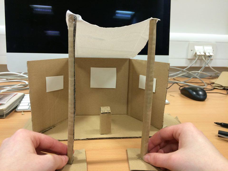
There would be a screen on the left that showed what the participants where suppose to try and draw.
The screen in the middle would project what is being drawn
and the screen on the right would show the grid (although this may be done different to stop people seeing the original drawing they are meant to be imitating.)

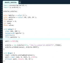
The post in the middle would be what holds the ardunio and has the control on top. The projector will also be in this post.

The video gives a idea of how it would be seen from the participants;


The post in the middle will consist of;
– Controllers (Circles) to guide the pen left, right, up and down
– Symbols to show users what controllers are what
– A button to clear the screen 
– A button to save finished sketch
– The ardunio board and laptop underneath the wood
– The projector

Sketch & Conductive paint

TEST 1

Original Test

To begin we reran the original controls. 


REFLECTION

+ Works well

Boring to use, not very exciting

Switches are difficult to use as too small and close together.


TEST 2

Using Paint to the X axis controller

By creating a straight line and placing the 5V wire at one end and the GND at the other/ the middle wire (A0) is held.


REFLECTION

+ Works well

 Still only 1 off the board

 Couldn’t use the whole screen


TEST 3

Using paint for the X and Y axis controller.

By replicating the same process as before for the other controller. this created reading for the Y axis s well.


RESULT

Test_3


REFLECTION

+ Works well

 Wouldn’t always use the full screen

 Was very jumpy, didn’t draw in straight line as it did before meaning the image would be distorted.
(however, this could be a good as it makes it more arty/ abstract, giving the piece some originality.)


TEST 4

Making the paint controllers circular

By simply drawing the paint into circular shapes and applying the wires in the same way.


RESULT

Test_4

REFLECTION

+ Works well

+ Bigger range across screen

+ the shape of the controllers are more representative of that on an original etch-e-sketch

 Still Jumpy


TEST 5

Using 2 people to control one axis

Person one; holds middle wire and person 2’s hand

Person two; holds person ones hand and moves their figure across one of the controllers

(test around with having to hold the wire connected to circuit.

IMG_0009 IMG_0011

RESULT

Test_5

REFLECTION

+ Works well

+ Bigger range across screen

+ Fun and requires co-operation

 Still Jumpy


REFLECTION 

The paint has been inputed into the circuit well. The shape makes it more representative of the old style as well as more responsive on the screen.

The controllers are still quite small though.

one other concern is that the middle wire requires it to be held to draw. This may be an inconvenience to the person using it.


Arduino & Processing

Step 1

The begin this we needed to set up ardunio so that the board would work with processing. To do this we used a sketch already set up by arduino called StandardFirmata. After resetting the arduino board we uploaded this. 


Step 2

The next stage we had to put code into processing.

Screen Shot 2016-03-19 at 12.24.53

Code Breakdown

The first lines of code tell processing to work with arduino
The Second section simply sets up what the page will look like, e.g. the background colour, pen colour and size. It also tells processing where to read the processing board from
The third section (void setup) tells processing the size of the screen, where to start the pen from (width/2 = centre). And finally what arduino port the input is coming from
The last section (void draw) tells processing how to read that particular input on the board (analog in this case), where to map the pen, and what the inputs are (penx and mouse)


Step 3

Set up the board.

Step1-1 Step1-2 Step1-5 Step1-6

From left to right of the poteniometer, the first wire(G) goes to 5V, second wire(O) goes to A0, and the third wire(Y) that goes to GND.


Step 4

Running processing and arduino.
This runs using JAVA.

The mouse will control the y axis (up and down) and the arduino will control the X (left and right)


Step 5

To add another poteniometer to replace the mouse, code needs to be added.
To do this, you need to change the original code that said ‘sensor’ to ‘sensor1’ all throughout the code.
Then add a sensor 2 that picks up the second poteniometer from A1
And lastly a PenY is needed, that will respond to Sensor 2

step2


Then the board will need to be set up.
Adding another  poteniometer the same as the first. the only difference is, the wire than originally ran to A0 (O), goes to A1 on the second poteniometer.
As there will now be 2 wires going to both 5v(G) and GND(Y), for both poteniometer, we put the wires going to 5V in the + line and GND to the -. ANd then one connecting wire from + to 5V and one from – to GND.

Step2-1 Step2-5 Step2-6 Step2-7


Finally run Processing using JAVA.
This time the first poteniometer (sensor 1) will do X axis and the second poteniometer (sensor 2) will do Y axis.


Step 6

To add the button
DO THIS

Reflection

After trying out the previous tutorial, we found that we could get the first one (the one with the etch e sketch frame) to work, but still found some faults in that the top of the screen couldn’t be used, and if you went to near the top, then it would erase what was on the screen.
With the second tutorial, the problem we found was that the code in arduino was not accurate enough for processing to find the arudino board port. Therefore it could not be used well


Therefore we have tried to develop this further b y creating basic processing code that could run the same system, but hopefully with less issues.

Current Problems

Although our first test with processing worked effectively with and without the paint, the next two didn’t seem to be able to run processing with the Arduino board.

we think this could be down to issues with the serial port. Processing isn’t registering the Arduino because we cant figure out ho to find out what serial port the Arduino is. This is something we are working on though, and is currently where we are up to in our experiments. 


 NEXT STEPS

  1. Work out the problem with processing and the serial port; why can’t it connect??
  2. Develop the experiments
  3. Figure out how to create X and Y readings in Arduino