Step 1
The begin this we needed to set up ardunio so that the board would work with processing. To do this we used a sketch already set up by arduino called StandardFirmata. After resetting the arduino board we uploaded this.
Step 2
The next stage we had to put code into processing.
Code Breakdown
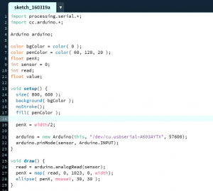
The first lines of code tell processing to work with arduino
The Second section simply sets up what the page will look like, e.g. the background colour, pen colour and size. It also tells processing where to read the processing board from
The third section (void setup) tells processing the size of the screen, where to start the pen from (width/2 = centre). And finally what arduino port the input is coming from
The last section (void draw) tells processing how to read that particular input on the board (analog in this case), where to map the pen, and what the inputs are (penx and mouse)
Step 3
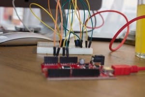
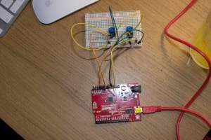
Set up the board.
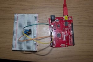
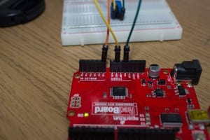
From left to right of the poteniometer, the first wire(G) goes to 5V, second wire(O) goes to A0, and the third wire(Y) that goes to GND.
Step 4
Running processing and arduino.
This runs using JAVA.
The mouse will control the y axis (up and down) and the arduino will control the X (left and right)
Step 5
To add another poteniometer to replace the mouse, code needs to be added.
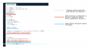
To do this, you need to change the original code that said ‘sensor’ to ‘sensor1’ all throughout the code.
Then add a sensor 2 that picks up the second poteniometer from A1
And lastly a PenY is needed, that will respond to Sensor 2
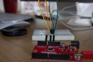
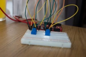
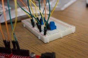
Then the board will need to be set up.
Adding another poteniometer the same as the first. the only difference is, the wire than originally ran to A0 (O), goes to A1 on the second poteniometer.
As there will now be 2 wires going to both 5v(G) and GND(Y), for both poteniometer, we put the wires going to 5V in the + line and GND to the -. ANd then one connecting wire from + to 5V and one from – to GND.
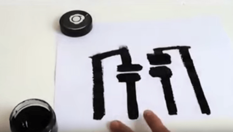
Finally run Processing using JAVA.
This time the first poteniometer (sensor 1) will do X axis and the second poteniometer (sensor 2) will do Y axis.
Step 6
To add the button
DO THIS


Recent Comments