Logo and Name Development


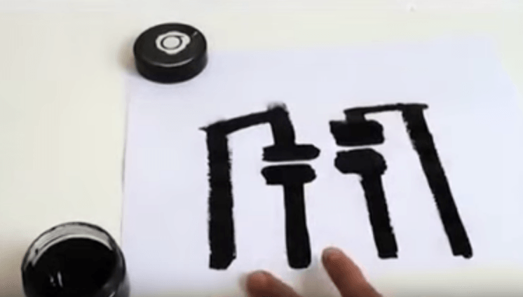
We know what we want the style of the logo to look like, namely a rough paint brush kind of style. Now we need the actual logo and a name for our product. The picture below shows a few first sketches and key words we could use.

logo_sketch_01

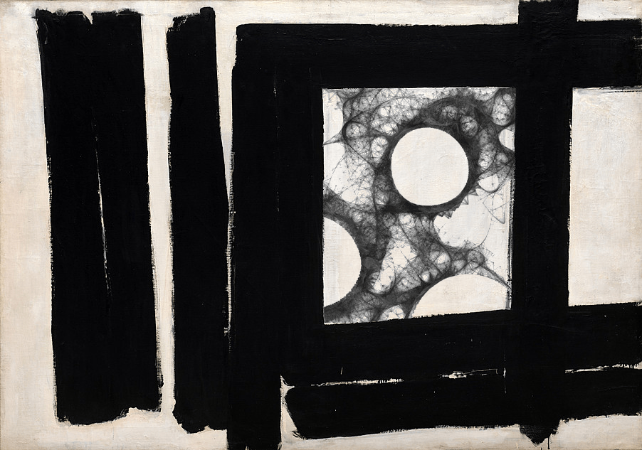
Leading on from this and influenced by our current visuals of the processing code, we came up with a very abstract logo idea. The circle is representing the circuit and our controls for the new etch a sketch, whilst the lines in the centre are a representation of a sketch.

logo_sketch_02

logo_sketch_vec-03

An abstract logo allows us to still think of a name. Following is a list of keywords that we could combine to name our product. We tried differnt variations but non of them were quite what we were looking for.

– Art

– Paint

– Brush

– Sketch

– Line

– Draw

– Play

– Game

– Retro

– Modern

– Combine

– Morph

– Scattered

– Altanative

– Create

– Collaborate

– Interact

– Finger

– Body

– Circuit

– Arduino

– Electronics

– Digital

– Cardboard

Finishing our little session Jas described our project as “edgy” -> “Edgy Sketch” (Saaayyy whhaaattt???)

We are well aware of it beeing a terribly cringy name but at the same time it gives it the certain something we need for people to remember it. I’m not saying it is the final name but it is the best we have at the moment. So going for the same style as already shown in example above and with the name “edgy sketch” we created some more logo sketches:

logo_sketch_03

logo_sketch_04

logo_sketch_05

…which I then converted in to vectors which look like this:

logo_sketch_vec-02  logo_sketch_vec-04logo_sketch_vec-01 logo_sketch_vec-05

Sketch & Conductive paint

TEST 1

Original Test

To begin we reran the original controls. 


REFLECTION

+ Works well

Boring to use, not very exciting

Switches are difficult to use as too small and close together.


TEST 2

Using Paint to the X axis controller

By creating a straight line and placing the 5V wire at one end and the GND at the other/ the middle wire (A0) is held.


REFLECTION

+ Works well

 Still only 1 off the board

 Couldn’t use the whole screen


TEST 3

Using paint for the X and Y axis controller.

By replicating the same process as before for the other controller. this created reading for the Y axis s well.


RESULT

Test_3


REFLECTION

+ Works well

 Wouldn’t always use the full screen

 Was very jumpy, didn’t draw in straight line as it did before meaning the image would be distorted.
(however, this could be a good as it makes it more arty/ abstract, giving the piece some originality.)


TEST 4

Making the paint controllers circular

By simply drawing the paint into circular shapes and applying the wires in the same way.


RESULT

Test_4

REFLECTION

+ Works well

+ Bigger range across screen

+ the shape of the controllers are more representative of that on an original etch-e-sketch

 Still Jumpy


TEST 5

Using 2 people to control one axis

Person one; holds middle wire and person 2’s hand

Person two; holds person ones hand and moves their figure across one of the controllers

(test around with having to hold the wire connected to circuit.

IMG_0009 IMG_0011

RESULT

Test_5

REFLECTION

+ Works well

+ Bigger range across screen

+ Fun and requires co-operation

 Still Jumpy


REFLECTION 

The paint has been inputed into the circuit well. The shape makes it more representative of the old style as well as more responsive on the screen.

The controllers are still quite small though.

one other concern is that the middle wire requires it to be held to draw. This may be an inconvenience to the person using it.


Example visuals for installation

We really like the rough and simple look of the conductive paint, as being used in the picture below.

Screen Shot 2016-03-21 at 18.13.55

As mentioned in an earlier blog post it reminds us of work by the artist Franz Kline. We are thinking to create a similar canvas for our etch a sketch to move away form the old visuals to a more modern and artistic one. We could create squares in which we can project the drawing of the digital etch a sketch and at the same time make the controllers, which we’ll be paining with electronic pain and that work like potentiometers, match the visual.

example

using a style like this also allows us to project several images at once. We can either have multiple etch a sketches working at once or show previously drawn ones in empty squares. As shown in the example below. If we go for several etch a sketches then we can have different styles for our brush. One that that might stick to the typical etch a sketch visuals and then others that are more abstract.

eg_visuals

Arduino & Processing

Step 1

The begin this we needed to set up ardunio so that the board would work with processing. To do this we used a sketch already set up by arduino called StandardFirmata. After resetting the arduino board we uploaded this. 


Step 2

The next stage we had to put code into processing.

Screen Shot 2016-03-19 at 12.24.53

Code Breakdown

The first lines of code tell processing to work with arduino
The Second section simply sets up what the page will look like, e.g. the background colour, pen colour and size. It also tells processing where to read the processing board from
The third section (void setup) tells processing the size of the screen, where to start the pen from (width/2 = centre). And finally what arduino port the input is coming from
The last section (void draw) tells processing how to read that particular input on the board (analog in this case), where to map the pen, and what the inputs are (penx and mouse)


Step 3

Set up the board.

Step1-1 Step1-2 Step1-5 Step1-6

From left to right of the poteniometer, the first wire(G) goes to 5V, second wire(O) goes to A0, and the third wire(Y) that goes to GND.


Step 4

Running processing and arduino.
This runs using JAVA.

The mouse will control the y axis (up and down) and the arduino will control the X (left and right)


Step 5

To add another poteniometer to replace the mouse, code needs to be added.
To do this, you need to change the original code that said ‘sensor’ to ‘sensor1’ all throughout the code.
Then add a sensor 2 that picks up the second poteniometer from A1
And lastly a PenY is needed, that will respond to Sensor 2

step2


Then the board will need to be set up.
Adding another  poteniometer the same as the first. the only difference is, the wire than originally ran to A0 (O), goes to A1 on the second poteniometer.
As there will now be 2 wires going to both 5v(G) and GND(Y), for both poteniometer, we put the wires going to 5V in the + line and GND to the -. ANd then one connecting wire from + to 5V and one from – to GND.

Step2-1 Step2-5 Step2-6 Step2-7


Finally run Processing using JAVA.
This time the first poteniometer (sensor 1) will do X axis and the second poteniometer (sensor 2) will do Y axis.


Step 6

To add the button
DO THIS

Reflection

After trying out the previous tutorial, we found that we could get the first one (the one with the etch e sketch frame) to work, but still found some faults in that the top of the screen couldn’t be used, and if you went to near the top, then it would erase what was on the screen.
With the second tutorial, the problem we found was that the code in arduino was not accurate enough for processing to find the arudino board port. Therefore it could not be used well


Therefore we have tried to develop this further b y creating basic processing code that could run the same system, but hopefully with less issues.