Arduino, Processing & sketching in Java

For this one, we wanted to try create a sketch again in processing and arduino than ran in Java. To do this we had to do it in different steps.


Step 1

First we had to set up the sketch in processing.

Testing-0681

After this we could begin to draw in Java using our mouse. From using the code we had, this created a black background with a green thick line.

Testing-0682


By changing some basic code, we could personalise the sketch to have the appearance we wanted. To make it look like a classic etch e sketch, we changed the background to white, the pen to black, and made the line thinner.

Testing-0683 Testing-0684


Step 2

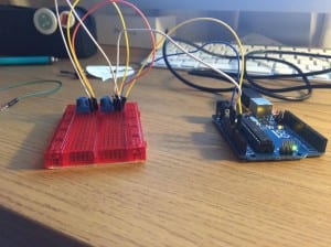
In the next step we had to add a button to control the drawing. To do this we had to build an Arduino circuit that included a tactile button.

Testing-0686

Testing-0687Testing-0688


We then had to build the code in Arduino and upload it. We then had to test out that this was working the way it needed to between the circuit and the code. To do this we ran the code and what we got was a continuous line of data from the arduino. When the button was pressed you can see the data from from 1 to 0.


**VIDEO TO BE UPLOADED**


Once this was done and tested, we then moved on to coding the processing. This code was given to us, and therefore we didn’t have to figure it out ourselves.
HOWEVER, as like the last experiment, we could figure out hoe to get the processing code to link to the Arduino.


This is still be tested now however, and is a work in progress. 


http://codasign.com/tutorials/etch-a-sketch-project/


Arduino, processing & Etch E SKetch

For the next experiment we wanted to make it more direct at our actual project aim. Therefore we decided to try and conduct the process of creating an etch e sketch through processing.

This is done by creating a circuit that contain to potentiometers. These had to be wired so that one analog was at port A0, on at 5V and one in the ground.

12823114_10156625566270287_2146922205_o


Once this was wired we open the example code created by arduino called Standard Firmata and uploaded it to our arduino board. we had to run this to get the max and minimum numbers of the potentiometers fro the processing code. This worked fine!

12837239_10156625566370287_888587315_o

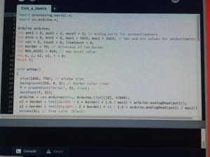
We then had to open up the code in processing, This was done by copying the sketch from the example below.

12171982_10156625566295287_1777766985_o

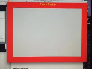
Once we rant his though we got the frame of the etch e sketch, but did not get the lines coming through from the arduino itself.

12842502_10156625566325287_487185205_o

This is a problem with the processing connecting to the arduino.


http://www.instructables.com/id/Virtual-Etch-A-Sketch/

Arduino, Processing a conductive paint

For our next experiment we began to start building code through Arduino and processing.

This involved firstly creating a simply circuit that connected with the board to the right inputs.

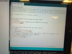
Then by simply copying code into Arduino, uploading it and running it you can see if the circuit is correct.


By uploading code from the Arduino processing download, it creates code that works with arduino.

From this we managed to create a circuit that has 2 inputs, a potentiometer and a photo-resistor. When the potentiometer was moved from left to right, the line on the screen moved to. When the photo-resistor was touched, the lines changed colour.

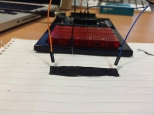
Once we have completed this, we then tried removing the potentiometer and added in the conductive paint. This was wired so that one end of the paint would equal the lowest value of the potentiometer and vice versa on the other side of the paint strip.

At first this was less reactive, however once we got going it began to work just as well.


http://www.instructables.com/id/How-to-control-a-Processing-sketch-with-two-Arduin/

Potentiometer Arduino & Conductive paint test

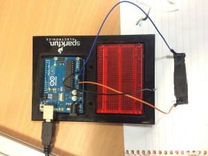
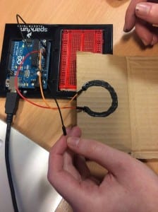
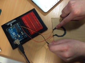
we wanted to begin exploring using paint as a sensor in creating data. By following this tutorial we created our own version.

12752127_10156572782760287_1274222487_o

12755194_10156572783065287_799068787_o

12751869_10156572783355287_106096163_o


Instead of using the the jumper wires that goes in A0 to touch the sensor, we held the end with one hand, whilst using the other hand to run along the circuit. This worked better than when we tried doing it directly with the wire.

Whilst this means that the paint can be interacted with directly using touch, it still require the A0 jumper wire to be held. Therefore finding a way to do this that is more efficient, or an alternative was is needed.


We also tried doing this same application but in a different shape.

12755297_10156572879660287_1908864435_o 12752152_10156572879795287_623270835_o


This could be applied when looking at the idea of creating an etch a sketch using the paint and arduino both concept and design of it)

Possible Ideas

A interactive platform that spreads the word through audience engagement and collaboration?????

The idea is to create interactive walls or posters for example that suites each company. As focused on media places, the idea of using technology to spread the word is fun, relevant and alternative??
By using key themes they have and the style and reason behind needing it, depends on how it is done.


Some mock-ideas:

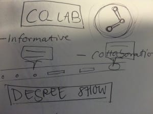
Co_lab

image2


As Co_lab is about new ways of learning and teaching things that could be included for this are;

  • Button across the bottom that require the audience to touch to set of a projection of what they do
  • By hovering over parts of the co_lab icon it lights up a particular part
  • Collaboration from the audience to make the whole Co_lab sign light up or appear (either by the buttons or hovering over all parts)
  • More text heavy giving information
  • the colour scheme of co_lab would be very prominent in the design/ projection/ whatever is done.


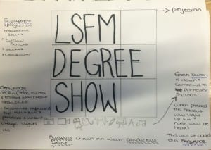
LSFM Degree Show


image1


As the degree show is all about showcasing and “showing off” the work the piece would try to be more glamorous.Things could include;

  • More graphic based and less information
  • All elements to represent each area of the LSFM field in symbols (buttons) along the middle
  • Sounds that go off when a symbol (button) is touched
  • An element of the degree show logo flashes (projects) when a button is pressed
  • Each time you press a different button a new part projects with the sound
  • requires the audience to light them all up and then you see the whole logo.